Online class
Google Meet room
Join the online session from the same meeting room whenever a class is scheduled.
Meeting code: gmy-mked-kvw
Join Google MeetProteus simulation and electronics solution
A focused project archive for the parkade IR detection work, count-up/count-down circuit evidence, solution PDFs, Proteus files, NotebookLM material, and installation resources in one clean place.
Project summary
The folder includes the assignment brief, staged Proteus solutions, exported circuit views, a final complete project file, NotebookLM presentation resources, IR sensor references, and setup notes for Proteus 8 Professional.
Student quick links
Online class
Join the online session from the same meeting room whenever a class is scheduled.
Meeting code: gmy-mked-kvw
Join Google MeetDirect message
Message Horizon Business directly for session questions, project support, or appointment follow-up.
WhatsApp: +27 75 453 1797
Message on WhatsAppVideo lessons
Open the project playlist for the current lessons and future videos as they are uploaded.
Open playlistPDF reference
Download the 00-99 UP/DOWN counter tables, LED control logic, seven-segment patterns, and pin meanings as a PDF.
Download PDFProject website
Use the hosted site to access resources, previews, videos, and contact details from any device.
Open live siteStudent learning sessions
Online session 01
This first online session is the main starting point for the student. More learning videos can be added here later as the project grows.
Continue to NotebookLM materialsStage 2 recording
This recording continues the online learning path for the project and focuses on the stage 2 work.
Open on YouTubeNotebookLM anatomy
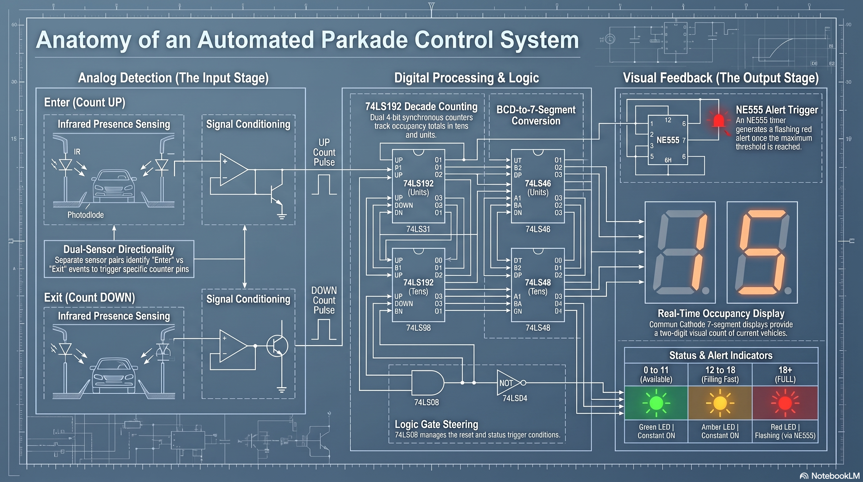
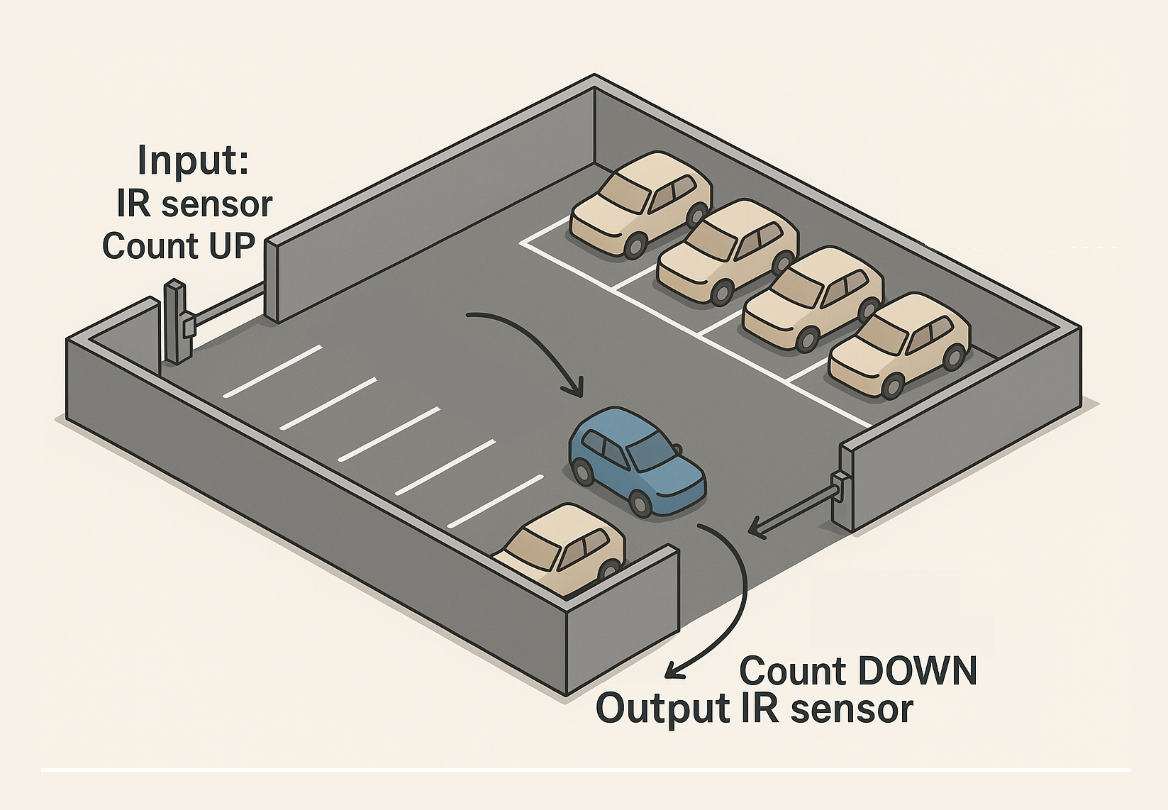
The generated anatomy material clarifies the project as a discrete parkade automation circuit: IR sensor pairs identify entry and exit movement, conditioning stages shape those signals into count pulses, counters track the current vehicle total, and the output stage drives display and alert indicators.
00-99 counter reference
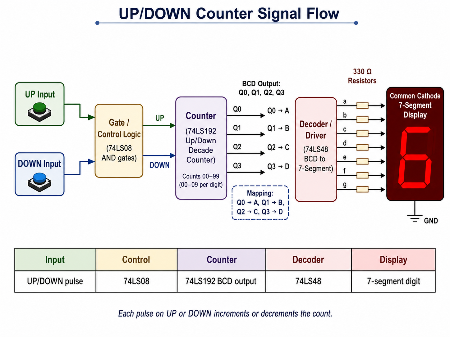
UP or DOWN pulses enter the 74LS192 counter, the BCD outputs feed the 74LS48 decoder, and the decoder drives the common-cathode seven-segment display through current-limiting resistors.
Counter outputs connect as Q0 to A, Q1 to B, Q2 to C, and Q3 to D. The segment states are ordered a b c d e f g, where 1 means ON and 0 means OFF.
The green, yellow, and flashing red indicators use only the tens counter A and B signals, so each colour remains stable while the ones digit moves inside that range.
Shows the path from manual UP/DOWN inputs through the control logic, BCD counter, decoder/driver, resistors, and common-cathode display.
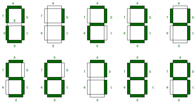
Visual reference for the a-g segment labels and which segments light for each decimal digit from 0 to 9.
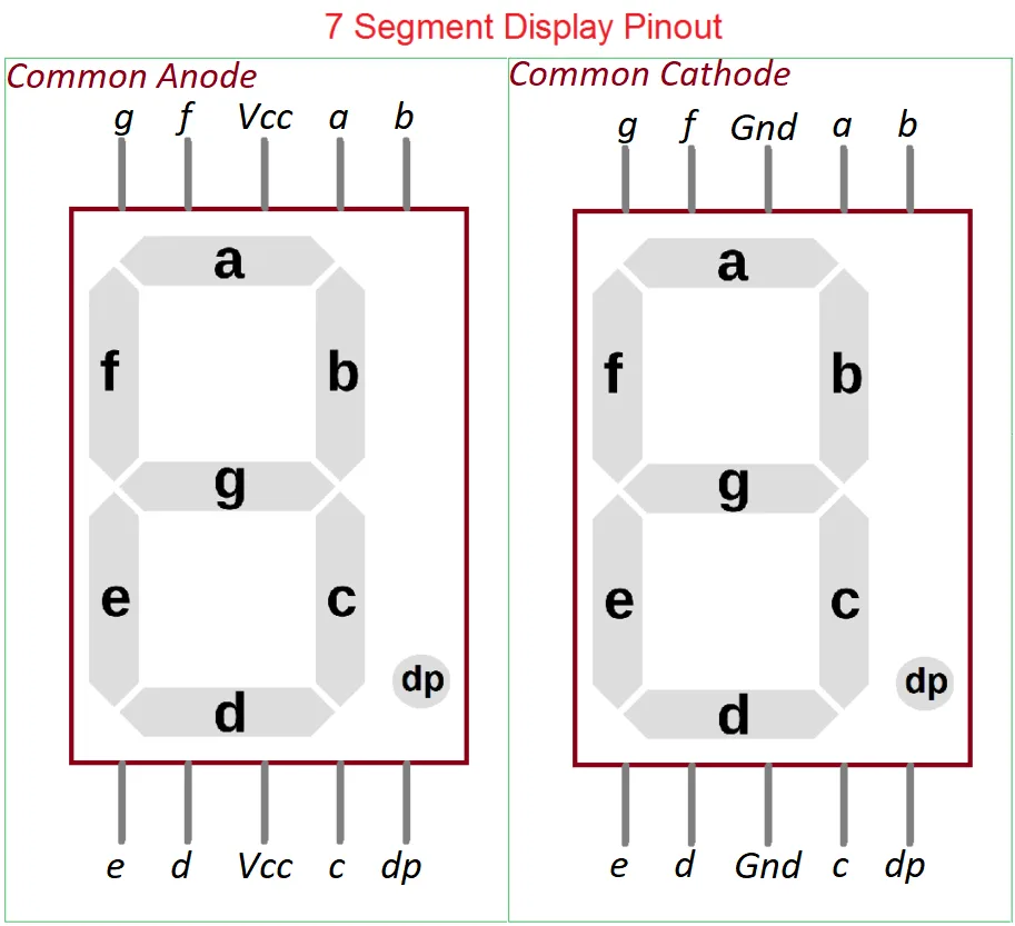
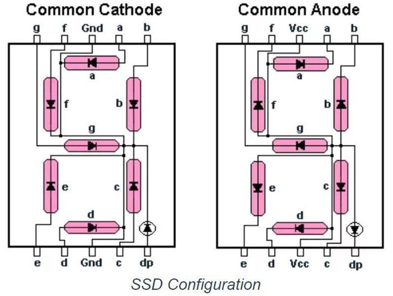
Compares common-anode and common-cathode pin labels, including segment pins a-g, decimal point, and the shared VCC or GND terminals.
Shows how the LED segments are wired inside common-cathode and common-anode displays, including the decimal-point LED path.
| UP input | DOWN input | Counter action | Display result |
|---|---|---|---|
| 0 | 0 | Holds the current value | Same number remains displayed |
| 1 pulse | 0 | Uses the UP pin and counts upward | Display increases by 1 |
| 0 | 1 pulse | Uses the DN pin and counts downward | Display decreases by 1 |
| 1 | 1 | Invalid control condition | Display may be unstable |
| Count range | A | B | Logic | Indicator |
|---|---|---|---|---|
| 00-09 | 0 | 0 | /A AND /B | Green LED ON |
| 10-19 | 1 | 0 | A AND /B | Yellow LED ON |
| 20-29 | 0 | 1 | /A AND B | Red LEDs flash through RL1 and NE555 |
| 30-39 | 1 | 1 | A AND B | Not selected in the shown logic |
For the 74LS48 with a common-cathode display, these values drive the a b c d e f g LED segments.
D0-D3 load a preset BCD value when PL is active LOW. Q0-Q3 output the BCD count. UP increments, DN decrements, MR resets to 0000, and TCU/TCD cascade carry or borrow between digits.
A-D receive Q0-Q3 from the counter. QA-QG drive segments a-g through 330 ohm resistors. LT, RBI, and BI/RBO are active-LOW display test or blanking controls.
74LS08 AND gates pass valid UP/DOWN pulses and detect LED ranges. 74LS04 inverter gates produce /A and /B so the circuit can select 00-09, 10-19, and 20-29 cleanly.
The common-cathode displays use segment pins a-g plus a common cathode tied to GND. Green and yellow LEDs show safe and warning ranges, while red LEDs D7 and D8 flash from the NE555 output.
Pin 3 OUT creates the flashing signal. TR, TH, and DC work with R8 and C2 to set the timing, while RESET enables or stops the timer.
All 74LS ICs need +5 V on VCC and 0 V on GND. Segment and LED resistors limit current, and the relay RL1 interfaces the red-range logic with the flashing LED stage.
These are the common DIP pin numbers used by the main ICs in the circuit. Seven-segment display pin numbers can vary by display model, so the segment labels a-g and common cathode remain the safest reference.
| IC / component | Physical pins | Pin labels | Use |
|---|---|---|---|
| 74LS192 | 15, 1, 10, 9 | D0, D1, D2, D3 | Parallel preset/load inputs for the counter. |
| 74LS192 | 3, 2, 6, 7 | Q0, Q1, Q2, Q3 | BCD output bits sent to the 74LS48 decoder. |
| 74LS192 | 5, 4, 11, 14, 12, 13 | UP, DN, PL, MR, TCU, TCD | Count clocks, parallel load, reset, carry, and borrow controls. |
| 74LS48 | 7, 1, 2, 6 | A, B, C, D | BCD inputs from Q0, Q1, Q2, and Q3. |
| 74LS48 | 13, 12, 11, 10, 9, 15, 14 | QA, QB, QC, QD, QE, QF, QG | Segment outputs that drive display segments a-g. |
| 74LS08 | 1, 2 -> 3; 4, 5 -> 6; 9, 10 -> 8; 12, 13 -> 11 | A, B -> Y | Four AND gate input and output groups. |
| 74LS04 | 1 -> 2; 3 -> 4; 5 -> 6; 9 -> 8; 11 -> 10; 13 -> 12 | Input -> output | Six inverter input and output groups. |
| NE555 | 1, 2, 3, 4, 5, 6, 7, 8 | GND, TR, OUT, RESET, CV, TH, DC, VCC | Timer power, trigger, output, reset, control, threshold, discharge, and supply pins. |
| 74LS IC power | 16 / 8 or 14 / 7 | VCC / GND | +5 V supply and 0 V ground, depending on the IC package. |
The table is generated from the same BCD and seven-segment patterns in the PDF. Tens and ones use the same 74LS192 to 74LS48 mapping.
| Count | Upper BCD | Upper segments | Lower BCD | Lower segments |
|---|
NotebookLM presentation
NotebookLM explanation
Watch the uploaded explanation video alongside the slide deck for a narrated overview of the parkade IR project.
Open on YouTubeDossier trail
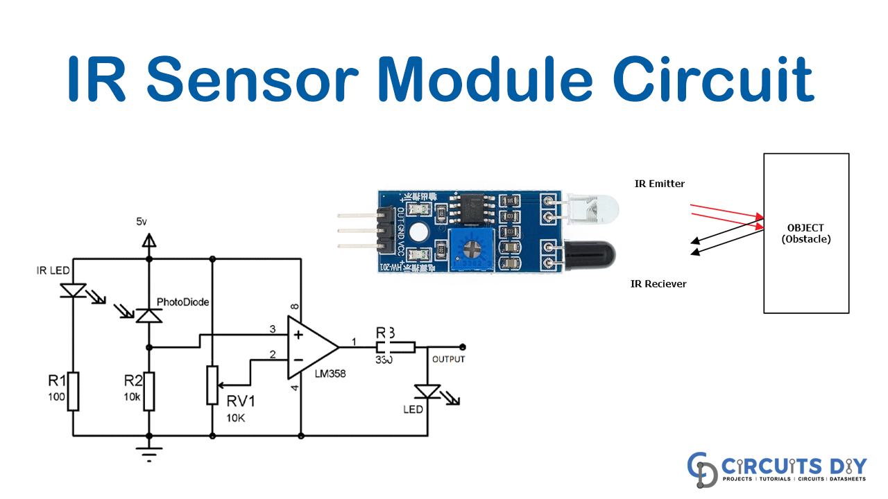
Start with the IR transmitter and receiver references that detect vehicles at entry and exit points.
Review the staged Proteus files that shape pulses and feed the up/down counting logic.
Use the exported views to inspect the seven-segment display path and visual status indicators.
Open the complete PDS project in Proteus and keep the PDF, PPTX, and supporting documents nearby for verification.
Project library
Proteus project ZIP
All Proteus source files, matching solution PDFs, exported images, and references from the Project folder in one download.
Added materials ZIP
One download containing the added PDF, all four counter/display reference images, and a note with the online session links.
NotebookLM visual
Generated overview showing the input, counting, display, and alert stages.
Counter visual
Visual walkthrough of the input, 74LS08 control logic, 74LS192 counter, 74LS48 decoder, resistors, and display output.
Display visual
Compact reference for the a-g segment labels and the lit segment pattern for each decimal digit.
Display pinout
Common-anode and common-cathode pin labels for segment pins a-g, decimal point, and shared supply terminals.
Display wiring
Internal LED wiring reference for common-cathode and common-anode seven-segment displays.
NotebookLM PDF
NotebookLM-generated PDF presentation for the parkade IR automation concept.
NotebookLM PPTX
Visible slide deck extracted from the NotebookLM PowerPoint, with the editable PPTX still available.
PDF reference
Corrected UP/DOWN control, BCD-to-decoder mapping, LED range logic, and pin meanings for the counter circuit.
The original project brief supplied with the control-system assignment.
Proteus source
The final integrated project file for Proteus 8.
Image
System-level project architecture for the IR sensor control solution.
Solution set
Grouped files: image preview, PDF solution, main Proteus source, and alternate PDS copy.
Solution set
Grouped files: Proteus source, matching PDF solution, and exported circuit image.
Solution set
Grouped files: Proteus source, PDF solution, exported image, and alternate image copy.
Reference image
Reference image for the IR sensor module used in the project context.
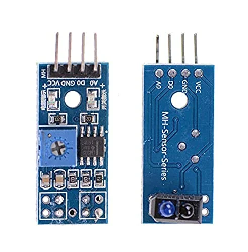
Reference image
Component reference image included with the Proteus project folder.
Reference image
Supporting IR sensor visual reference from the project folder.
Proteus setup
Extract the installer, run setup, apply the supplied license, then validate each stage independently before integrating the full design.
1. Download Proteus 8 Professional.
2. Open the relevant PDS project file.
3. Keep detector, counter, and status stages separate during validation.
4. Avoid Check for Updates because this installation is version-locked.
.jpg)